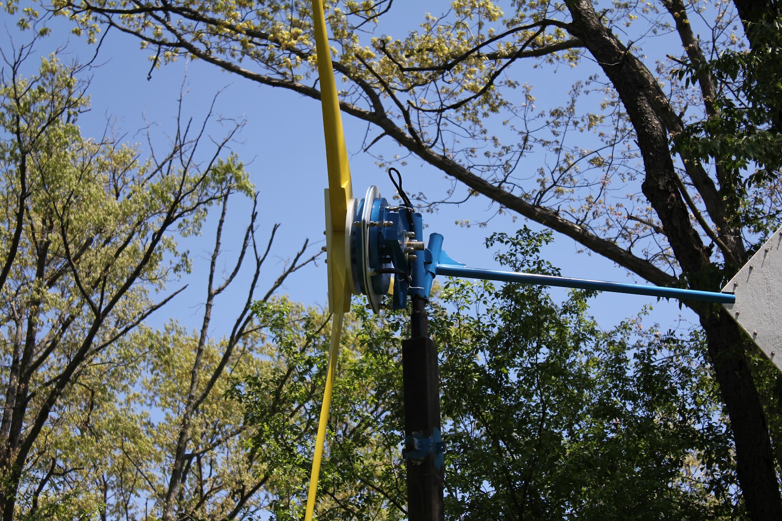
Here are some photos of the original turbine after being up just over 8 months. A little background info is in order;
During that 8 months this turbine has seen scorching hot summer temperatures, freezing cold winter temps, Hurricane Sandy with winds over 80kph, and being struck by flying ice at 70kph!
Worse then the ice, was someone leaving the brake/charge/freewheel switch in freewheel mode during a prolonged high wind period that saw wind speeds that peaked at over 10ms. I have no idea how fast the rotor was turning, just that it was WAY too fast.
The snowplow incident.......the turbine sits on a very short 5m tower, and is no more then 7m from the road. After our Christmas snowstorm the plow went by doing it's job, and the wall of ice, snow, and gravel hit the turbine square on. I don't know how much the ice and snow weighed, but it wasn't good for one of the blades.
Enjoy the pictures, shit happens, and it's all repairable. When I get a chance I'll post some info on the new 800w turbine. I've made some changes based on info gathered from the mule (a test unit) that should increase longevity, make maintenance a little easier, and increase power.
Pictures to follow shortly.....sorry!
Friday, February 22, 2013
Monday, September 17, 2012
Ferrite Design
I've been using Neomags to build turbines based on Huge Piggots original recipe with good results.
The last 3m used (24) 2"x1"x.5" N42 magnets ($17.50 each), with a total cost (here in Canada) of $420, just for magnets. That's a lot of change and certainly impacts the total cost of the project.
Ferrite magnets on the other hand are cheap, $1 for the same size as the neo. With less magnetic flux I'll need to use more magnets, but even going to 96 magnets (each magnet will be 2"x2"x.5" or 2"x2"x1" depending on testing) will cost $300 less.
Some of the criteria is that it must use the standard 3m frame, have a narrow stator (in order to close the air gap), be 300mm or less in diameter, and operate at 24v.
The first test uses 80 turns of 14awg, triangular shape, with pin centres of 40mm. This should allow me to keep the diameter of the mag rotors to 300mm. The smaller diameter will allow me to close the air gap without fears of contact between the mag rotors and the stator.
The pic below shows the coils mounted to a soldering board. The board is easy to make, and takes less time then trying to keep the coils in position while soldering. Now when the soldering is done and the coils removed they're in perfect position.
Below is a pic of the ferrite dimensions compared to a neo stator. As well as being smaller in diameter it's thinner as well. Thickness of the ferrite is 15.3mm, and the neo version is 16.1mm. Again, this will help me to close the air gap, helping push power up. The added bonus is that the new stator will also use less epoxy in the casting process, again helping to lower costs.
Resistance for the ferrite stator is .8ohms per phase. Intending to be operated at 24v, this should give me approx 30amps, and 720w. IF I exceed 500w I'll be happy.
A ferrite design putting out 500w is perfect for turbines in the remote areas of Mexico. Plenty of power with a good site, and a lower cost of materials.
As I continue with this build I'll update the posts with numbers from testing.
The last 3m used (24) 2"x1"x.5" N42 magnets ($17.50 each), with a total cost (here in Canada) of $420, just for magnets. That's a lot of change and certainly impacts the total cost of the project.
Ferrite magnets on the other hand are cheap, $1 for the same size as the neo. With less magnetic flux I'll need to use more magnets, but even going to 96 magnets (each magnet will be 2"x2"x.5" or 2"x2"x1" depending on testing) will cost $300 less.
Some of the criteria is that it must use the standard 3m frame, have a narrow stator (in order to close the air gap), be 300mm or less in diameter, and operate at 24v.
The first test uses 80 turns of 14awg, triangular shape, with pin centres of 40mm. This should allow me to keep the diameter of the mag rotors to 300mm. The smaller diameter will allow me to close the air gap without fears of contact between the mag rotors and the stator.
 |
| Ferrite project coil. 80 turns, 14AWG wire, 40mm pin centers |
 |
| Coils mounted to a soldering board. Makes soldering so much easier. |
 |
| Comparison of the ferrite stator to the 800w neo stator. |
 |
| Nine coils set out prior to soldering. |
As I continue with this build I'll update the posts with numbers from testing.
Sunday, August 5, 2012
Beware of Advertisements
Recently I spent some time going over ads for micro turbines, and there's lots of interesting claims out there. So before anybody parts with their hard earned cash some wind math is in order.
A case in point is an ad for a micro turbine from my local Kijiji;
"We build these wind turbines to provide 1200watts of power. They are suitable for charging 12/24/48 volt battery systems....in winds over 4-5mph (6.4-8kph or 1.7-2.2ms)...Brand new 24” (.61m) blades."
Wow, 1.2kW from a 48" (1.22m) diameter blade. Unless you live in a wind tunnel you'll never see that kind of an output.
The most energy you can extract is 59.3% of the total kinetic energy contained in the wind. Most small scale turbines operate much lower then that, while industrial turbines approach it, but still can't get there.
According to the Bertz co-efficient you would need a sustained wind of 27mph (43kph or 11.9ms) to get 1200w from a 48" (1.2m) blade. To come to this number we need to use some wind math;
---------------------------------------------------------------------------------------------------------
First we need the swept area of the rotor;
Area = π x (blade diameter x blade diameter) / 4
Using the above ad - 3.1416 x (1.22 x 1.22) / 4 = 3.1416 x 1.4884 / 4 = 1.17m2
---------------------------------------------------------------------------------------------------------
Power in watts = .5 x air density x swept area x wind velocity3
Where - air density (@ sea level) = 1.23kg/m3
- swept area in m2
- velocity in meters per second
So.......... .5 x 1.23 x 1.17 x 5.5ms3 (5.5ms is my areas average wind speed)
.5 x 1.23 x 1.17 x 166.37 = 117.91 watts
--------------------------------------------------------------------------------------------------------------------------
Now lets try doubling the blade area;
.5 x 1.23 x 2.34 x 5.5ms3 = .5 x 1.23 x 2.34 x 166.37 = 239.42 watts
*Doubling the blade diameter roughly doubles the power output.
--------------------------------------------------------------------------------------------------------------------------
Now lets use the original swept area and double the wind speed;
.5 x 1.23 x 1.17 x 11ms3 = .5 x 1.23 x 1.17 x 1331 = 957.72 watts
*Doubling the wind speed roughly increases 8x the original power output. Yet we're still not at the 1200watts from the original ad.
--------------------------------------------------------------------------------------------------------------------------
Using 43kph wind speeds;
.5 x 1.23 x 1.17 x 11.95ms3 = .5 x 1.23 x 1.17 x 1706.49 = 1227.9 watts
Wind speeds like this happen very rarely in most areas of the world.
Below is a spreadsheet showing output at different wind speeds using the above blade size.

Another spreadsheet using a 3m diameter blade.

Windspeeds remain the same, just the blade diameter changes. Huge difference in power output.
So, beware of advertisements, things are not always as they seem.
If you have any questions just add a comment and I'll do my best to answer them.
Wednesday, June 20, 2012
The start of Positive Energy
The thought was to use wind/hydro power to help people in the state of Oaxaca, Mexico achieve energy stability. The area is susceptible to severe flooding during the rainy season, washing away roads and pathways, often for extended periods of time.
There are small pockets of people who live on the mountainsides, who, during the worst have no electricity. Not for pumping or boiling water, security/safety lighting, or for charging cell phones. Rainy season creates islands in the mountains.
This is where the idea for Positive Energy was born.
Most of the coastal area between Puerto Angel and Salina Cruz is blessed with an abundant wind resource. Winds in this area average between 5.3 m/s to over 8.5 m/s. With a 3 meter blade, and a wind of 5.3 m/s, the kinetic energy available is 639 watts. But at 8.5 m/s, the same sized blade can produce over 2,700 watts!
The other natural resource in this area is an abundance of spring fed streams in the mountains and numerous natural waterfalls (cascadas). Most of the water falls I've visited drop 2 - 5 meters into a standing pool cut into the rock.
Each one of these natural drops provides a possibility for electrical production using the same generator as the wind turbine, adapted for hydro use.
At this point I have a location in my known world that needs electricity, the resources are there, but not a generator to produce electricity. What's needed is an easy to manufacture unit. One that can be built using easy to source products, does not require an engineering degree to maintain, and is strong and robust. Enter Hugh Piggott.
This gentlemen has been building wind turbines for over 30 years. Perfecting his craft through trial and error (both his and others) has led him to produce a book, aptly titled "A Wind Turbine Recipe". As I've said, this book culminates years of practical, hands on knowledge of what works, and what doesn't. Now I have a way of producing power.
Now the pieces are starting to fall together, the place, the resource, and the way to make it happen. But wait, these people have no money for a project like this. Most people in this area are fortunate to make $100 week, let alone "extra cash" for this.
There has to be a way. In searching the web for ideas I found out that others are doing the same thing as I type. People have successfully started programs building wind turbines for the electrification of rural areas, so it can be done.
There are small pockets of people who live on the mountainsides, who, during the worst have no electricity. Not for pumping or boiling water, security/safety lighting, or for charging cell phones. Rainy season creates islands in the mountains.
This is where the idea for Positive Energy was born.
Most of the coastal area between Puerto Angel and Salina Cruz is blessed with an abundant wind resource. Winds in this area average between 5.3 m/s to over 8.5 m/s. With a 3 meter blade, and a wind of 5.3 m/s, the kinetic energy available is 639 watts. But at 8.5 m/s, the same sized blade can produce over 2,700 watts!
 |
| The Isthmus of Tehuantepec, Mex Wind Resource Map, NREL |
Each one of these natural drops provides a possibility for electrical production using the same generator as the wind turbine, adapted for hydro use.
 |
| Map showing the rivers around Copalita |
 |
| Scoraigwind is Hugh Piggotts web site. Copies of his book can be purchased here. |
This gentlemen has been building wind turbines for over 30 years. Perfecting his craft through trial and error (both his and others) has led him to produce a book, aptly titled "A Wind Turbine Recipe". As I've said, this book culminates years of practical, hands on knowledge of what works, and what doesn't. Now I have a way of producing power.
Now the pieces are starting to fall together, the place, the resource, and the way to make it happen. But wait, these people have no money for a project like this. Most people in this area are fortunate to make $100 week, let alone "extra cash" for this.
There has to be a way. In searching the web for ideas I found out that others are doing the same thing as I type. People have successfully started programs building wind turbines for the electrification of rural areas, so it can be done.
Monday, May 28, 2012
An Idea

I'm a very fortunate man. My family and I had the opportunity to live in southern Mexico for an extended period. While we were there we had the time to slow down and pursue things other then work. One of the things I wanted to pursue was an interest in making electricity by "unconventional" means. So I took a course on Turbine Analysis.
It was great for teaching me "wind math" and the theory of using the wind to make power, but I'm not interested in running a corporate wind farm. All this new information could be put to use, but how?
I'm a fan of Mexico. I know what the papers say, and I've driven through the reality of it, but that doesn't change my opinion. In fact it strengthens it. Mexicans for the most part are warm, friendly people, hard working and honest. Of all the new friends and people we met down there the ones we're closest to are Mexican nationals. And most of them, by our standards are extremely poor.
That is if they live in an area that has reliable power to use.
Could a small scale wind turbine produce enough electricity in these remote locations?
 |
| Open voltage testing, 800w axial flux generator. January 2012. |


Tuesday, May 22, 2012
Mock Up


Magnet Rotors

Above is a picture of one of the magnet rotors. The rotor is 1/2" steel plate with 12 neodymium magnets "crazy" glued to it. The heavy steel plate helps to ensure that the magnet flux stays between the two rotors where it's needed to make power.
The next step is to encapsulate all of the magnets in epoxy, this serves two purposes. The first one is to make sure that the magnets stay where they're supposed to be. The second one is that neo mags are very susceptible to corrosion and being fully embedded in epoxy guarantees moisture stays out.
Bearing Hub
The bearing hub used in this turbine is a standard four bolt, 1,000lb trailer hub. The studs are punched out to allow for the stainless steel threaded rod that will be used to bolt it all together.
The rear face where the magnet rotor mounts was machined flat in order to give the rotor a "true" surface to mount to. The only other modification was to remove the rear seal to ruduce friction.

One of my concerns was the mount between the hub and the frame assembly. Simply welding the shaft to the frame would not offer the support I wanted. There are multiple ways of overcoming this; welded collars to increase weld area, web style supports welded between the shaft and frame on the rear section, etc.
The mount I used in the end is shown below. The hub shaft has a welded collar installed first, then the steel plate is welded to the shaft and the collar.

When the hub is installed into the frame a second piece of steel plate is installed and 4 1/2" bolts are used to mount the assembly.

This set up gives me the added ability of removing the generator section from the frame easily allowing me to experement with different gennies or mounting systems (stationary bike perhaps?).
Thursday, May 17, 2012
Rectifier, Brake Box

The generator produces 3phase AC voltage (alternating current), but storing the electricity in batteries requires DC voltage(direct current). The job of the rectifier is to convert the electricity from ac to dc.
The output wires from the generator are fastened to the 3 connector terminal block on the left side of the photo. Each terminal is 1 phase of the 3 phase output.
From here 3 individual wires travel up to a charge/freewheel/brake switch mounted through the front panel. This is a high amperage switch that allows the user to control the flow of electricity from the turbine. The emergency brake function of this switch is a critical feature allowing the turbine to be "stopped" for regular maintenance or emergency situations.
From the switch the electricity flows to three single phase rectifiers mounted on a large aluminum heat sink. This is where the conversion from ac to dc takes place. Leaving the rectifiers the wires terminate at a 2 connector terminal block, this is where the charge controller will connect to.
Three position, nine pole switch.

Single phase rectifier.


Steel Frame
Here is a picture of the steel work. The horizontal "rectangular" section on the left is where the hub will be mounted. The centre round pipe (yaw tube) is welded to a piece of angle iron in front of it. The angled section is offset backwards by 4 degrees, slightly tilting the blades back, increasing the distance between the blade tips and the tower. The tube on the right is for the tail boom. It too is offset from the yaw tube, but this time it's to the right. The offset between the hub, tail boom and the rotational centre (yaw tube) allow the turbine to "furl" itself when the winds get strong. This furling allows the turbine to bend in the middle (lower picture), effectively turning the blades away from the wind preventing damage from over speeding blades.


This image gives a good idea of the rear leaning tilt of the generator frame section. It also shows the rear tilt of the boom pivot.


All threaded hardware is 1/2" 304 stainless steel. If this turbine was intended for a coastal site it would have been built with 314 stainless in order to better handle damp salt air.

Below is a picture of the threaded hardware contents for this unit. The four long bolts are for the generator/hub assembly, three shorter bolts are the stator mounts and the four small bolts are for the bearing hub to frame mount. Before the final tightening each threaded piece has a liberal drop of thread locker applied to it.

Coil, Stator Mould
This is one of the finished coils for this turbine. For the intended output of 800w / 48 volts, each coil contains over 100 turns of 14 gauge copper "magnet" wire. These coils are connected together, giving smooth 3 phase electricity.

Below is a picture of the original prototype drawing and mould for the stator. There are 9 coils in this particular stator. After the coils have been laid out epoxy is added to the mould, encapsulating the coils, and a lid is tightly fixed into place.


Monday, August 15, 2011
Stator coil winder
These drawings are not to scale, so please use the specified dimensions.


The handle and the stand are the two easiest pieces to start with. The handle was made by bending a piece of 8mm threaded rod at 90deg angles marked 15cm apart. I made my stand to clamp to my work bench, but any configuration can be used so long as it's sturdy. Drill a 10mm hole in the centre of one end of the stand to insert the threaded rod through.
Thread two nuts onto the rod and spin them down to the 90deg bend, then tighten them together. Install a 10mm washer, the stand, another washer and finally two more nuts, jamming them together also. The picture below explains it well.

For the jig itself start by marking a horizontal line on the plywood, 70mm down from the top edge. Draw a second horizontal line 42mm past the first line. Next I drew a vertical line 70mm from the side edge, and a second line 26mm after the first. This gives a small rectangle showing the four corner marks to drill the 8mm holes for the dowels. From these corner marks draw two diagonal lines connecting the corners, giving the centre mark.
Using the center mark a drew a 120mm circle around all of it, and I drew a second 120mm circle on the wood beside the first one. Only the face of one disc needs to have the hole markings on it.
Cut the circles out with a jigsaw, sandwich them together (with the marked face out) and then clamp them tightly together. Using the drill start with the centre hole, drilling through both cheek faces at once. When the hole is finished install an 8mm bolt through it to help keep everything aligned. Next drill the four corner points, installing wooden dowels as each hole is finished.
Double checking at this point the outside of the dowel holes should measure 46mm x 30mm. This size is specific to the size of the magnets being used, the centre opening of the finished coil needs to be the same OD of the magnets.
Next draw three horizontal lines, the first 4mm from the top edge, next at 26mm and the last at 30mm.
Moving to the edge of the wood draw three vertical lines at 4mm, 42mm, and 46mm, giving a rectangle inside a rectangle. Using the same method as before draw diagonal lines connecting the corners giving the center of the part were the 8mm hole is drilled. With the jigsaw cut out the larger rectangle (30mm x 46mm). Use a 1" chisel to notch out the corners, allowing space for the dowels. This could also be done with the saw, either way works well.

Subscribe to:
Posts (Atom)