Monday, May 28, 2012

An Idea


I'm a very fortunate man. My family and I had the opportunity to live in southern Mexico for an extended period. While we were there we had the time to slow down and pursue things other then work. One of the things I wanted to pursue was an interest in making electricity by "unconventional" means. So I took a course on Turbine Analysis.

It was great for teaching me "wind math" and the theory of using the wind to make power, but I'm not interested in running a corporate wind farm. All this new information could be put to use, but how?

I'm a fan of Mexico. I know what the papers say, and I've driven through the reality of it, but that doesn't change my opinion. In fact it strengthens it. Mexicans for the most part are warm, friendly people, hard working and honest. Of all the new friends and people we met down there the ones we're closest to are Mexican nationals. And most of them, by our standards are extremely poor.

And electricity is extremely expensive (by Cad standards), 33 cents kWh. Way too expensive for most families to have much more then basic electrical requirements.
That is if they live in an area that has reliable power to use.

The rainy season starts in May and continues until September, and when it rains, it RAINS. Dry creek beds fill with torrents of water washing anything in their path out of the way. Rocks 2m across and bigger get moved downstream with the water. So do roads, telephone poles and hydro lines. For 3 months (or more) some people in the mountains may as well be on an island. With no roads, no communication and no electricity they are truly isolated until repairs are made. Which in Mexico may take a while.

Wind however they have in abundance. Being a coastal area the winds blow almost constantly. Maybe I had my answer?

Could a small scale wind turbine produce enough electricity in these remote locations?

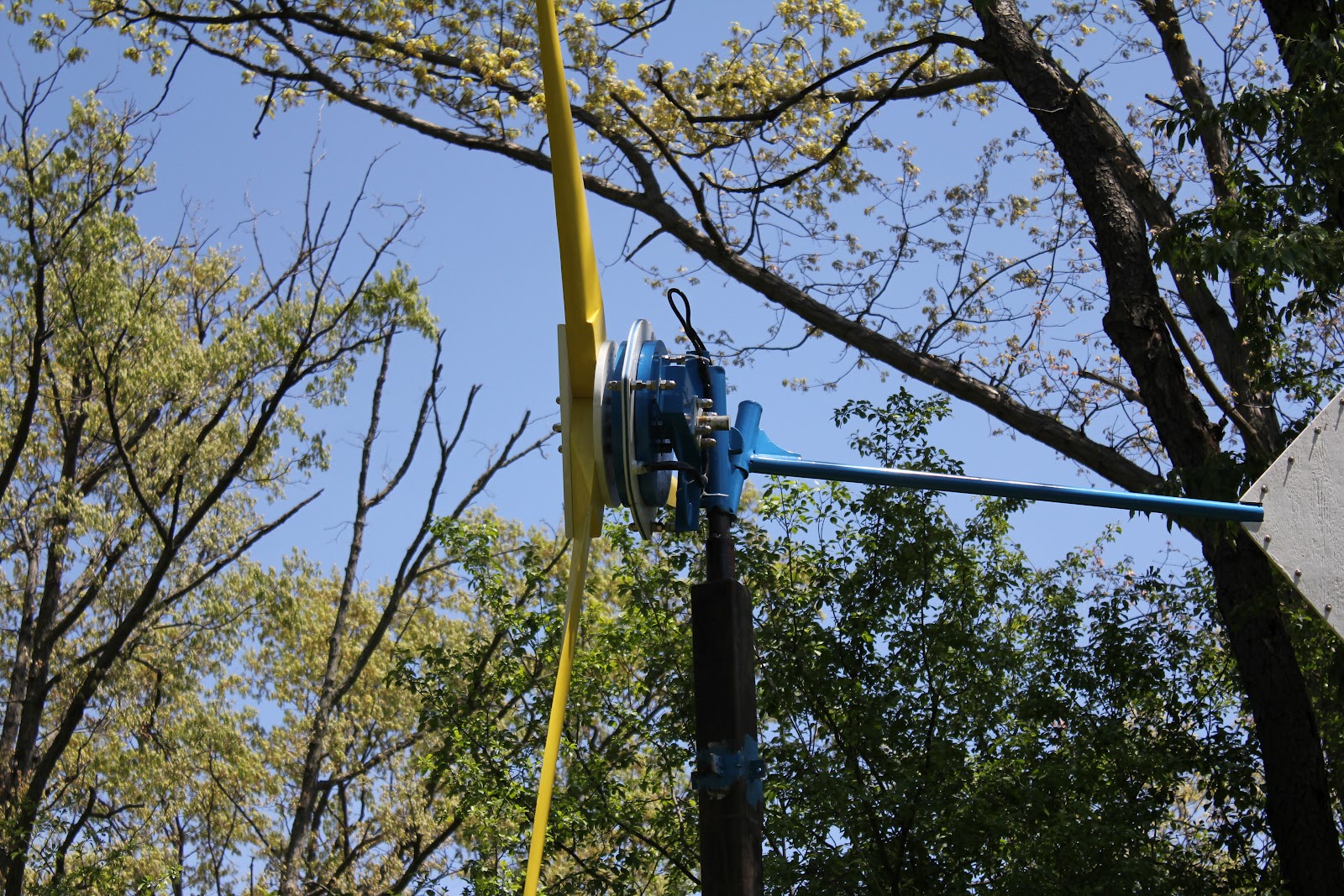
Open voltage testing, 800w axial flux generator. January 2012.


Installation


Turbine Assembly


3 Meter Blades


Blades and Hub


Tuesday, May 22, 2012

Mock Up


These pics where taken of a "mock up" before the real assembly took place. The wooden sections are the mould making cut outs. The magnet rotor mould had 1" x 2" slots cut out in order to be used as a jig while installing the magnets.

Magnet Rotors


Above is a picture of one of the magnet rotors. The rotor is 1/2" steel plate with 12 neodymium magnets "crazy" glued to it. The heavy steel plate helps to ensure that the magnet flux stays between the two rotors where it's needed to make power.

The next step is to encapsulate all of the magnets in epoxy, this serves two purposes. The first one is to make sure that the magnets stay where they're supposed to be. The second one is that neo mags are very susceptible to corrosion and being fully embedded in epoxy guarantees moisture stays out. 

Bearing Hub

The bearing hub used in this turbine is a standard four bolt, 1,000lb trailer hub. The studs are punched out to allow for the stainless steel threaded rod that will be used to bolt it all together.

The rear face where the magnet rotor mounts was machined flat in order to give the rotor a "true" surface to mount to. The only other modification was to remove the rear seal to ruduce friction.


One of my concerns was the mount between the hub and the frame assembly. Simply welding the shaft to the frame would not offer the support I wanted. There are multiple ways of overcoming this; welded collars to increase weld area, web style supports welded between the shaft and frame on the rear section, etc.
The mount I used in the end is shown below. The hub shaft has a welded collar installed first, then the steel plate is welded to the shaft and the collar.


When the hub is installed into the frame a second piece of steel plate is installed and 4 1/2" bolts are used to mount the assembly.


This set up gives me the added ability of removing the generator section from the frame easily allowing me to experement with different gennies or mounting systems (stationary bike perhaps?).


Thursday, May 17, 2012

Rectifier, Brake Box


The generator produces 3phase AC voltage (alternating current), but storing the electricity in batteries requires DC voltage(direct current). The job of the rectifier is to convert the electricity from ac to dc.
The output wires from the generator are fastened to the 3 connector terminal block on the left side of the photo. Each terminal is 1 phase of the 3 phase output. 
From here 3 individual wires travel up to a charge/freewheel/brake switch mounted through the front panel. This is a high amperage switch that allows the user to control the flow of electricity from the turbine. The emergency brake function of this switch is a critical feature allowing the turbine to be "stopped" for regular maintenance or emergency situations.
From the switch the electricity flows to three single phase rectifiers mounted on a large aluminum heat sink. This is where the conversion from ac to dc takes place. Leaving the rectifiers the wires terminate at a 2 connector terminal block, this is where the charge controller will connect to.

Three position, nine pole switch.

Single phase rectifier.

 Note; the picture below is to show a rectifier and heat sink together. It is not the one being used in this wind turbine. This is a single, 3 phase rectifier, the turbine uses three single phase rectifiers allowing for simple, low cost repairs. And in the event that one unit fails, there will still be output, only at a reduced level.


Steel Frame

Here is a picture of the steel work. The horizontal "rectangular" section on the left is where the hub will be mounted. The centre round pipe (yaw tube) is welded to a piece of angle iron in front of it. The angled section is offset backwards by 4 degrees, slightly tilting the blades back, increasing the distance between the blade tips and the tower. The tube on the right is for the tail boom. It too is offset from the yaw tube, but this time it's to the right. The offset between the hub, tail boom and the rotational centre (yaw tube) allow the turbine to "furl" itself when the winds get strong. This furling allows the turbine to bend in the middle (lower picture), effectively turning the blades away from the wind preventing damage from over speeding blades.


This image gives a good idea of the rear leaning tilt of the generator frame section. It also shows the rear tilt of the boom pivot.

All threaded hardware is 1/2" 304 stainless steel. If this turbine was intended for a coastal site it would have been built with 314 stainless in order to better handle damp salt air.


Below is a picture of the threaded hardware contents for this unit. The four long bolts are for the generator/hub assembly, three shorter bolts are the stator mounts and the four small bolts are for the bearing hub to frame mount. Before the final tightening each threaded piece has a liberal drop of thread locker applied to it.


Coil, Stator Mould

This is one of the finished coils for this turbine. For the intended output of 800w / 48 volts, each coil contains over 100 turns of 14 gauge copper "magnet" wire. These coils are connected together, giving smooth 3 phase electricity.


Below is a picture of the original prototype drawing and mould for the stator. There are 9 coils in this particular stator. After the coils have been laid out epoxy is added to the mould, encapsulating the coils, and a lid is tightly fixed into place.